Tag Archives: BER

Bit Error Rate of 64-QAM in AWGN

64-QAM is an important modulation scheme being used in WiMAX and LTE. It allows for transmission of 6 bits symbol which results in higher bit rate and spectral efficiency. The calculation of bit error rate of 64-QAM is a bit tricky as there are many different formulas available with varying degrees of accuracy. Here, we first calculate the bit error rate (BER) of 64-QAM using a simulation and then compare it to the theoretical curve for 64-QAM.

%%%%%%%%%%%%%%%%%%%%%%%%%%%%%%%%%%%%%%%%%%%%%%%%%%%%%%
% FUNCTION TO CALCULATE 64-QAM BER USING SIMULATION
% n_bits: Input, number of bits
% EbNodB: Input, energy per bit to noise PSD
% ber: Output, bit error rate
% Copyright RAYmaps (www.raymaps.com)
%%%%%%%%%%%%%%%%%%%%%%%%%%%%%%%%%%%%%%%%%%%%%%%%%%%%%%
function[ber]= M_QAM(n_bits,EbNodB);
M=64;
k=log2(M)
EbNo=10^(EbNodB/10);
x=transpose(round(rand(1,n_bits)));
h1=modem.qammod(M);
h1.inputtype='bit';
h1.symbolorder='gray';
y=modulate(h1,x);
n=randn(1,n_bits/k)+j*randn(1,n_bits/k);
y=y+sqrt(7/(2*EbNo))*n.';
h2=modem.qamdemod(M)
h2.outputtype='bit';
h2.symbolorder='gray';
h2.decisiontype='hard decision';
z=demodulate(h2,y);
ber=(n_bits-sum(x==z))/n_bits
return
%%%%%%%%%%%%%%%%%%%%%%%%%%%%%%%%%%%%%%%%%%%%%%%%%%%%%%
%%%%%%%%%%%%%%%%%%%%%%%%%%%%%%%%%%%%%%%%%%%%%%%%%
% CALCULATE 64-QAM BER USING FORMULA
%%%%%%%%%%%%%%%%%%%%%%%%%%%%%%%%%%%%%%%%%%%%%%%%%
EbNodB=0:2:16;
EbNo=10.^(EbNodB/10);
k=6;
M=64;
x=sqrt(3*k*EbNo/(M-1));
Pb=(4/k)*(1-1/sqrt(M))*(1/2)*erfc(x/sqrt(2));
semilogy(EbNodB,Pb)
%%%%%%%%%%%%%%%%%%%%%%%%%%%%%%%%%%%%%%%%%%%%%%%%%

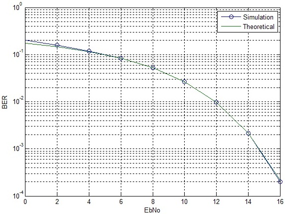
Using the above functions the BER of 64-QAM is calculated as shown below. Also shown is the constellation diagram of 64-QAM after addition of noise.
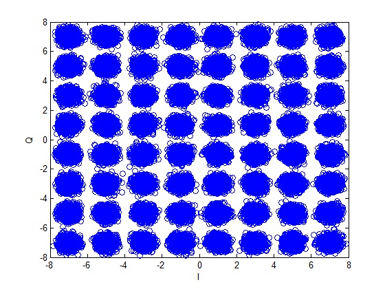
64-QAM Constellation
64-QAM BER
64-QAM BER

It is observed that the theoretical curve almost overlaps the simulation results. There is only a very small difference at very low signal to noise ratio. The BER of 64-QAM at 16dB is approximately equal to the BER for QPSK at 8dB. Therefore the 64-QAM can only be used in scenarios where there is a very good signal to noise ratio.

In this post we have used built in MATLAB functions for modulation and demodulation. In future posts we try to build up the simulation without using these functions!

OFDM Modulation and Demodulation (AWGN)

OFDM modulation works on the principle of converting a serial symbol stream to a parallel symbol stream with each symbol from the parallel set modulating a seperate carrier. The spacing between the carriers is 1/T where T is the duration of the OFDM symbols (without cyclic prefix). This guarantees orthogonality of the carriers i.e. there is no interference between carriers. The addition of orthogonal carriers modulated by parallel symbol streams is equivalent to taking the IFFT of the parallel symbol set. At the receiver the inverse operation of FFT is performed and the parallel symbol streams are converted to serial symbol streams.

The main advantage of this scheme is that one carrier (or set of carriers) may undergo severe fading but other carriers would be able to carry data. Equalization on these narrowband channels is also much easier than equalization of one wideband channel. Intersymbol Interference (ISI) which effects the signal in the time domain is removed by adding a guard period between symbols, called cyclic prefix (which we will discuss later).

OFDM Modulator Demodulator

We demonstrate the performance of OFDM with QPSK modulation in a simple AWGN channel. Although the true benefits of OFDM are really visible when we have a fading channel but this simple example would serve as a good starting point.

%%%%%%%%%%%%%%%%%%%%%%%%%%%%%%%%%%%%%%%%%%%%%%%%%%%%%%%%%%
% FUNCTION TO CALCULATE BER OF OFDM IN AWGN
% seq_len: Input, number of OFDM symbols
% n_carr: Input, number of subcarriers 
% EbNo: Input, energy per bit to noise PSD
% ber: Output, bit error rate
% Copyright RAYmaps (www.raymaps.com)
%%%%%%%%%%%%%%%%%%%%%%%%%%%%%%%%%%%%%%%%%%%%%%%%%%%%%%%%%%
function[ber]=OFDM_err(seq_len,n_carr,EbNo)
for n=1:seq_len
si=2*(round(rand(1,n_carr))-0.5);
sq=2*(round(rand(1,n_carr))-0.5);
s=si+j*sq;
s_ofdm=sqrt(n_carr)*ifft(s,n_carr);
wn=(1/sqrt(2*10^(EbNo/10)))*(randn(1,n_carr)+j*randn(1,n_carr));
r=s_ofdm+wn;
s_est=fft(r,n_carr);
si_est=sign(real(s_est));
sq_est=sign(imag(s_est));
ber1(n)=(n_carr-sum(si==si_est))/n_carr;
ber2(n)=(n_carr-sum(sq==sq_est))/n_carr;
end
ber=mean([ber1 ber2]);                                                           
return
%%%%%%%%%%%%%%%%%%%%%%%%%%%%%%%%%%%%%%%%%%%%%%%%%%%%%%%%%
OFDM BER AWGN

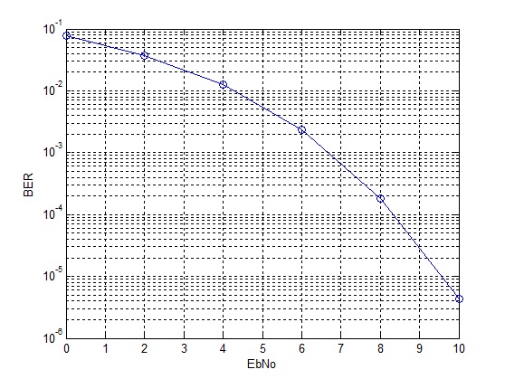
As expected in an AWGN channel the BER performance of OFDM is simply the BER performance of QPSK in AWGN. With cyclic prefix, some of the transmitted energy would be wasted and the BER performance would be a bit worse (to be discussed in future posts).

Alamouti Scheme

So we have seen that multiple transmit antennas provide the same gain as multiple receive antennas if the channel state information can be fed back to the transmitter. But what if the channel state information cannot be fed back to the transmitter (or it can be done but not quickly enough). The solution to this problem is the so called “Alamouti Scheme”. In this scheme two symbols are simultaneously transmitted from two transmit antennas and in the next time slot phase shifted versions of these two symbols are transmitted over the two transmit antennas. The channel is assumed to be quasi static i.e. it is static over the duration of two time slots but then changes for the next two time slots. A combining scheme is used at the receiver which separates the two symbols.

%%%%%%%%%%%%%%%%%%%%%%%%%%%%%%%%%%%%%%%%%%%%%%%%%%%%%%%
% l: Length of symbol sequence
% EbNo: Energy per bit to noise power spectral density
% ber: Output bit error rate
% Copyright www.raymaps.com
%%%%%%%%%%%%%%%%%%%%%%%%%%%%%%%%%%%%%%%%%%%%%%%%%%%%%%%

function[ber]=err_rate7(l,EbNo)
s1i=2*(round(rand(1,l))-0.5);
s1q=2*(round(rand(1,l))-0.5);
s1=s1i+j*s1q;
s2i=2*(round(rand(1,l))-0.5);
s2q=2*(round(rand(1,l))-0.5);
s2=s2i+j*s2q;

n1=(1/sqrt(2*10^(EbNo/10)))*(randn(1,l)+j*randn(1,l));
n2=(1/sqrt(2*10^(EbNo/10)))*(randn(1,l)+j*randn(1,l));
h1=(1/sqrt(2))*((randn(1,l))+j*(randn(1,l)));
h2=(1/sqrt(2))*((randn(1,l))+j*(randn(1,l)));

r1=h1.*(sqrt(1/2)*s1)+h2.*(sqrt(1/2)*s2)+n1;
r2=-h1.*conj(sqrt(1/2)*s2)+h2.*conj(sqrt(1/2)*s1)+n2;
s1_=conj(h1).*r1+h2.*conj(r2);
s2_=conj(h2).*r1-h1.*conj(r2);
s1i_=sign(real(s1_));
s1q_=sign(imag(s1_));

ber1=(l-sum(s1i==s1i_))/l;
ber2=(l-sum(s1q==s1q_))/l;
ber=mean([ber1 ber2]);
return
%%%%%%%%%%%%%%%%%%%%%%%%%%%%%%%%%%%%%%%%%%%%%%%%%%%%%%%
Alamouti Scheme

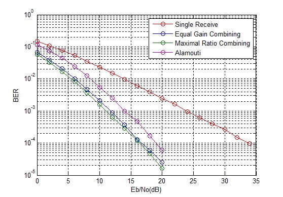
It is observed that this scheme is 3dB worse than MRC (and transmit diversity with CSI). This reason for this is that unlike MRC the signals are transmitted from two transmit antennas thus the power is halved at each transmit antenna (this scheme is also 3dB worse than transmit diversity with CSI at transmitter because although both schemes transmit half the power from each source but in this scheme the noise power is doubled due to the combining scheme working over two time slots).

Transmit Diversity using Channel State Information

We saw that equal gain combining and maximal ratio combining result in tremendous improvement in bit error rate performance in a Rayleigh fading channel. These are receive diversity schemes i.e. schemes that work with multiple receive antennas. Now let us turn our attention to schemes that work with multiple transmit antennas. We know that the main aim of a combining scheme is to coherently add the signals. If the same signal is transmitted from multiple transmit antennas the resulting signals would not add up coherently when they arrive at the receiver (remember that each path introduces a random phase shift). One solution to this problem is that the channel state information (CSI) be fed back to the transmitter. So if this done quickly enough, before the channel state changes, the phase of the signals at the transmit side could be pre-adjusted so that when these signals arrive at the receiver they combine constructively.

%%%%%%%%%%%%%%%%%%%%%%%%%%%%%%%%%%%%%%%%%%
function[ber]=err_rate5(l,EbNo)
si=2*(round(rand(1,l))-0.5);
sq=2*(round(rand(1,l))-0.5);
s=si+j*sq;
n=(1/sqrt(2*10^(EbNo/10)))*(randn(1,l)+j*randn(1,l));
h1=(1/sqrt(2))*((randn(1,l))+j*(randn(1,l)));
h2=(1/sqrt(2))*((randn(1,l))+j*(randn(1,l)));
sr1=(1/sqrt(2))*s.*(conj(h1)./abs(h1));
sr2=(1/sqrt(2))*s.*(conj(h2)./abs(h2));
r=h1.*sr1+h2.*sr2+n;
si_=sign(real(r));
sq_=sign(imag(r));
ber1=(l-sum(si==si_))/l;
ber2=(l-sum(sq==sq_))/l;
ber=mean([ber1 ber2]);
return
%%%%%%%%%%%%%%%%%%%%%%%%%%%%%%%%%%%%%%%%%%

It is observed that above scheme has exactly the same bit error rate performance as equal gain combining. The reason for this is that in the above scheme the noise at the receiver is halved (single receiver means single noise component) but the transmit power is also halved from each of the transmit antennas (to keep the total transmit power same). Thus it does not matter whether the phase adjustment happens at the receiver or the transmitter. But the important question is that can the channel state information be fed back to the transmitter quickly enough?

Maximal Ratio Combining in Rayleigh Fading

We just saw the advantage an equal gain combiner (a combining scheme that just adds the signals after co-phasing them) provides in a Rayleigh fading channel. Lets now look at a variant of this scheme called maximal ratio combining (MRC). In MRC the signals arriving at the receivers are weighted by the channel gains i.e. a stronger signal is weighted more than a weaker signal before combining. It must be noted that in an actual system the received signals are both scaled and phase shifted thus an MRC receiver multiplies the received signals by the complex conjugate of the channel coefficients before addition.

%%%%%%%%%%%%%%%%%%%%%%%%%%%%%%%%%%%%%%%%%%%%%%%
function[ber]=err_rate4(l,EbNo)
si=2*(round(rand(1,l))-0.5);
sq=2*(round(rand(1,l))-0.5);
s=si+j*sq;
n1=(1/sqrt(2*10^(EbNo/10)))*(randn(1,l)+j*randn(1,l));
h1=(1/sqrt(2))*((randn(1,l))+j*(randn(1,l)));
n2=(1/sqrt(2*10^(EbNo/10)))*(randn(1,l)+j*randn(1,l));
h2=(1/sqrt(2))*((randn(1,l))+j*(randn(1,l)));
r1=abs(h1).*s+n1;
r2=abs(h2).*s+n2;
r=abs(h1).*r1+abs(h2).*r2;
si_=sign(real(r));
sq_=sign(imag(r));
ber1=(l-sum(si==si_))/l;
ber2=(l-sum(sq==sq_))/l;
ber=mean([ber1 ber2]);
%%%%%%%%%%%%%%%%%%%%%%%%%%%%%%%%%%%%%%%%%%%%%%%

OR (using the complex channel coefficient)

%%%%%%%%%%%%%%%%%%%%%%%%%%%%%%%%%%%%%%%%%%%%%%%
function[ber]=err_rate4(l,EbNo)
si=2*(round(rand(1,l))-0.5);
sq=2*(round(rand(1,l))-0.5);
s=si+j*sq;
n1=(1/sqrt(2*10^(EbNo/10)))*(randn(1,l)+j*randn(1,l));
h1=(1/sqrt(2))*((randn(1,l))+j*(randn(1,l)));
n2=(1/sqrt(2*10^(EbNo/10)))*(randn(1,l)+j*randn(1,l));
h2=(1/sqrt(2))*((randn(1,l))+j*(randn(1,l)));
r1=h1.*s+n1;
r2=h2.*s+n2;
r=conj(h1).*r1+conj(h2).*r2;
si_=sign(real(r));
sq_=sign(imag(r));
ber1=(l-sum(si==si_))/l;
ber2=(l-sum(sq==sq_))/l;
ber=mean([ber1 ber2]);
return
%%%%%%%%%%%%%%%%%%%%%%%%%%%%%%%%%%%%%%%%%%%%%%%

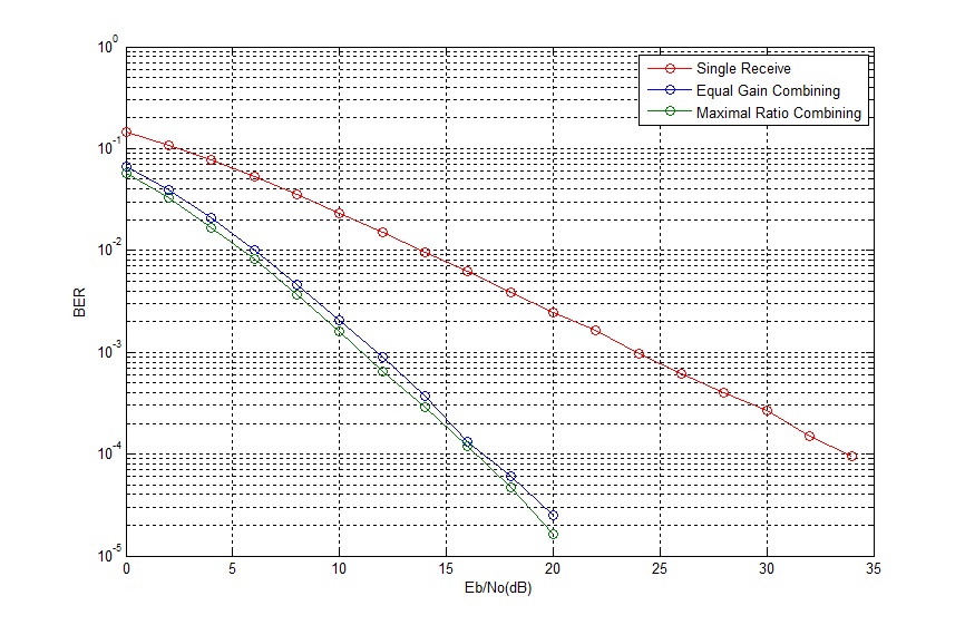
We see that there is an incremental improvement in BER using MRC instead of EGC (1dB can sometimes be significant).

Maximal Ratio Combining

Note:

1. The performance of MRC is the same using both the techniques given above.

2. Phase rotation of the noise component does not effect the BER performance.


Equal Gain Combining in Rayleigh Fading

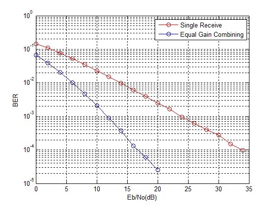
When wireless signals travel from a single transmit antenna to multiple receive antennas they experience different fading conditions. While signal from one path may experience a deep fade the signal from another path may be stronger. Therefore selecting the stronger of the two signals (selection combining, threshold combining) or adding the signals (equal gain combining, maximal ratio combining) would always yield much better results (lower bit error rate). However, there must be sufficient spacing between the different receive antennas for the received signals to be dissimilar (uncorrelated). In the simulation below we consider a 1-Tx, 2-Rx scenario. The signals arriving at the two receive antennas are added together before detection.

%%%%%%%%%%%%%%%%%%%%%%%%%%%%%%%%%%%%%%%%
function[ber]=err_rate4(l,EbNo)
si=2*(round(rand(1,l))-0.5);
sq=2*(round(rand(1,l))-0.5);
s=si+j*sq;
n1=(1/sqrt(2*10^(EbNo/10)))*(randn(1,l)+j*randn(1,l));
h1=(1/sqrt(2))*((randn(1,l))+j*(randn(1,l)));
n2=(1/sqrt(2*10^(EbNo/10)))*(randn(1,l)+j*randn(1,l));
h2=(1/sqrt(2))*((randn(1,l))+j*(randn(1,l)));
r1=abs(h1).*s+n1;
r2=abs(h2).*s+n2;
r=r1+r2;
si_=sign(real(r));
sq_=sign(imag(r));
ber1=(l-sum(si==si_))/l;
ber2=(l-sum(sq==sq_))/l;
ber=mean([ber1 ber2]);
return
%%%%%%%%%%%%%%%%%%%%%%%%%%%%%%%%%%%%%%%%
Equal Gain Combining

Note:

1. Not only the signals on the two paths experience uncorrelated fading but the the noise at the receiver front ends is also uncorrelated.

2. In reality the signals over both the paths would also experience random phase shifts but these can be removed before the combining process at the receiver.