Tag Archives: 4G

Antenna Radiation Pattern and Antenna Tilt

An introductory text in Communication Theory would tell you that antennas radiate uniformly in all directions and the power received at a given distance ‘d’ is proportional to 1/(d)^2. Such an antenna is called an isotropic radiator. However, real world antennas are not isotropic radiators. They transmit energy in only those directions where it is needed. The Gain of a antenna is defined as the ratio of the power transmitted (or received) in a given direction to the power transmitted in that direction by an isotropic source and is expressed in dBi.

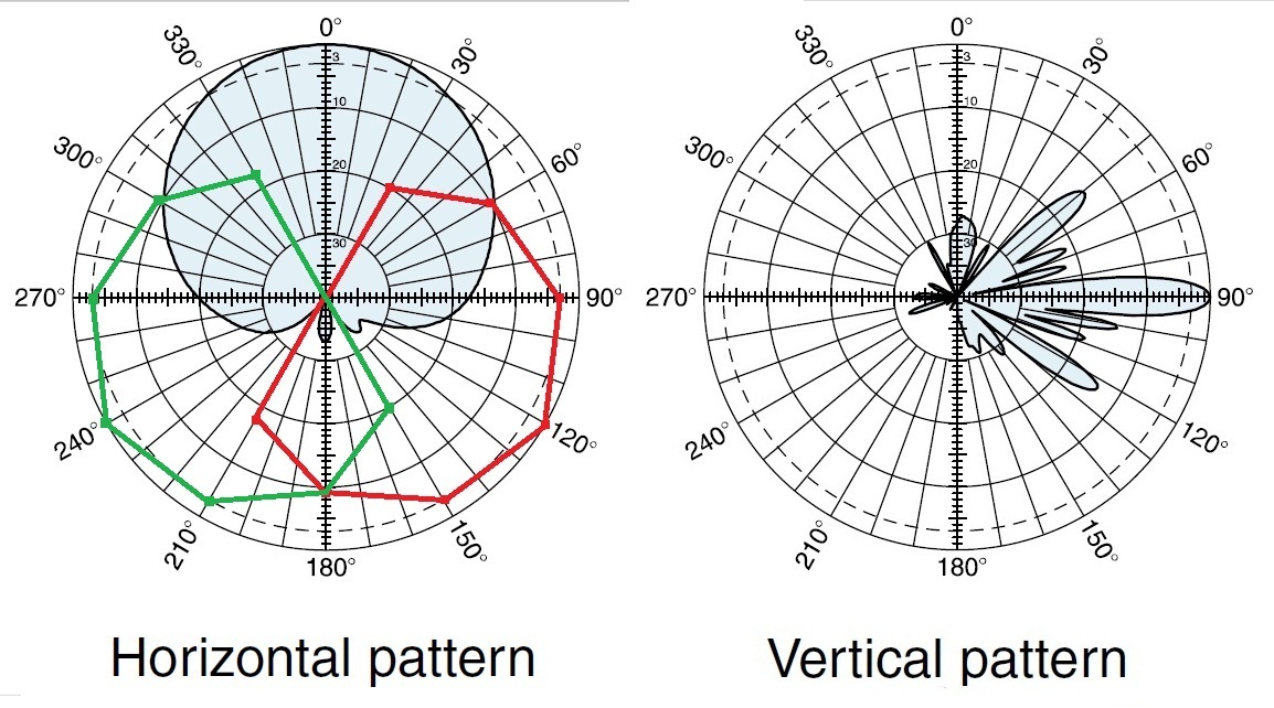
Although antenna Gain is a three dimensional quantity, the Gain is usually given along horizontal and vertical planes passing through the center of the antenna. The Horizontal and Vertical Gain patterns for a popular base station antenna Kathrein 742215 are shown in the figure below.

Kathrein 742215 Gain Pattern

The actual Gain is given with respect to the maximum Gain which is a function of the frequency e.g. in the 1710-1880 MHz band the maximum Gain has a value of 17.7dBi. Another important parameter is the Half Power Beam Width (HPBW) which has values of 68 degree and 7.1 degree in the horizontal and vertical planes respectively. HPBW is defined as the angle in degrees within which the power level is equal to or above the -3 dB level of the maximum.

Also shown in the above figure are approximate Horizontal Gain patterns for two antennas that have been rotated at 120 degrees and 240 degrees. Together these three antennas cover the region defined as a cell. There would obviously be lesser coverage in areas around the intersection of two beams.

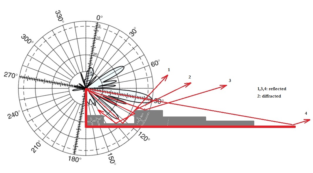
A somewhat more interesting pattern is in the vertical direction where the HPBW is only 7.1 degrees. Thus it is very important to direct this beam in the right direction. A perfectly horizontal beam would result in a large cell radius but may also result in weak signal areas around the base station. A solution to this problem is to give a small tilt to the antenna in the downward direction, usually 5-10 degrees. This would reduce the cell radius but allow for a more uniform distribution of energy within the cell. In reality the signal from the main beam and side lobes (one significant side lobe around -15 dB) would bounce off the ground and buildings around the cell site and spread the signal around the cell.

Antenna Tilt of 10 Degrees

The above figure gives a 2D view of signal propagation from an elevated antenna with a downward tilt of 10 degrees in an urban environment.
LTE Path Loss at 700 MHz

In the previous post we had compared the path loss of LTE at 728 MHz and 1805 MHz in a free space line of sight channel. This is a very simplistic channel model which tells us that ratio of the received signal strengths at these frequencies can be simply found as:

(f1/f2)^2=(1805/728)^2=6.15

That is the received signal strength at 728 MHz is 6.15 times higher than the received signal strength at 1805 MHz.

Now let us consider a more realistic channel model known as the COST-231 model. According to this model the path loss (difference between the transmit power and receive power) is given as:

L=46.3+33.9*log10(f)-13.82*log(ht)-a+(44.9-6.55*log10(ht))*log10(d)+C

where

f=frequency in MHz (0.1500 MHz – 2000 MHz)

ht=base station antenna height in m (30 m – 200 m)

hr=mobile station antenna height in m (1 m – 10 m)

d=transmit receive separation in km (1 km – 20 km)

C=3 dB for metropolitan centres

and mobile station antenna correction factor is given as:

a=3.2*log10(11.75*hr)^2-4.97

Using the above equations with ht=30 m, hr=1 m and d=1 km the path loss at 728 MHz and 1805 MHz is found out to be 100.63 dB and 114.00 dB respectively i.e. there is a gain of 13.37 dB when using the lower frequency. In simpler terms the received signal at 728 MHz would be 21.72 times stronger than the signal at 1805 MHz.

Such a remarkable improvement in signal strength or in signal to noise ratio (SNR) has the potential of increasing the throughput four folds. For example at an SNR of 1.5 dB QPSK 1/2 would give a throughput of 6.00Mbps whereas at an SNR of 14.7 dB a modulation coding scheme (MCS) of 64QAM 2/3 would result in a throughput of 24.01 Mbps.

Modulation Coding Schemes

Verizon 4G LTE Deployment Within California

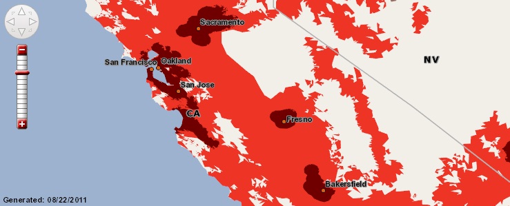
We have previously looked at the birds eye view of 4G LTE coverage within the US. We know that Verizon 4G services are now available to more than 50% of the US population. However, geographically, the service is only available in very small islands of population. Now, we take a closer look at 4G LTE coverage within California.

LTE Coverage in CA

We see that the coverage is available in most of the population centers such as Sacramento, San Francisco, Oakland, San Jose, Fresno and Bakersfield. Further south the coverage is also available in areas around Los Angeles and San Diego. But what is not shown on this map is that there is no coverage in many smaller cities such as Stockton, Modesto, Santa Rosa and Visalia. Also there is no coverage on the highways connecting these cities e.g. there is no coverage on I-5 which runs along the length of the state.

Bottomline: You may get very good LTE coverage when you are at home but don’t expect the same when you are on the highway. You will most probably have to fall back to 3G.


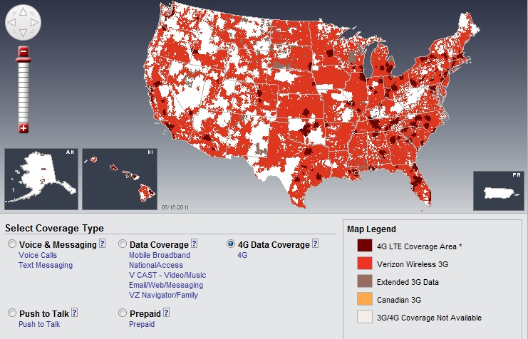
Verizon 4G LTE Deployment within the US

Verizon Wireless 4G LTE is now available to 160 million people with coverage in 117 cities within the US. This has been achieved within eight months of the initial deployment. Verizon hopes to increase the coverage to 185 million people by the end of 2011. The company claims that with its current deployment strategy users can experience data rates of 5-12Mbps on the downlink and 2-5Mbps on the uplink. When users do not have access to the 4G LTE network the phones will automatically switch to 3G which is available around most of the US.

LTE Coverage

This push to 4G creates a big gap between the developed and underdeveloped parts of the world where many nations have still not migrated from 2G to 3G.