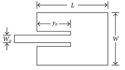
A microstrip antenna can be designed using either the transmission line model or the cavity model (more complex models also exist that suit a particular design). We here demonstrate the transmission line model since it is fairly simple to implement and results in antenna designs with reasonably good performance in terms of return loss and efficiency.

The design starts with selecting the operating frequency, selecting a substrate with the required permittivity, and defining the width of the substrate. Thick substrates with low permittivity result in antenna designs with high efficiency and large bandwidths. Thin substrates with high permittivity lead to a smaller antenna size but with a lower bandwidth and a high-radiation loss. The tradeoffs between substrate thickness and permittivity and antenna bandwidth and efficiency have been discussed in the literature.
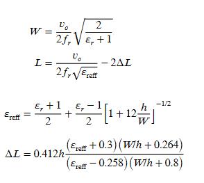
According to the transmission line model, the length L and width W of the patch are calculated as
Although the design of the patch is quite simple, the design of the feeding mechanism is not that straightforward. There are four possible methods that can be used:
(1) Microstrip-line feed
(2) Probe feed
(3) Aperture-coupled feed
(4) Proximity-coupled feed
Reference
[1] Yasir Ahmed, Yang Hao, and Clive Parini, “A 31.5 GHz Patch Antenna Design for Medical Implants,” International Journal of Antennas and Propagation, vol. 2008, Article ID 167980, 6 pages, 2008.
Author: Yasir
More than 20 years of experience in various organizations in Pakistan, the USA, and Europe. Worked with the Mobile and Portable Radio Group (MPRG) of Virginia Tech and Qualcomm USA and was one of the first researchers to propose Space Time Block Codes for eight transmit antennas. Have publsihed a book “Recipes for Communication and Signal Processing” through Springer Nature.
