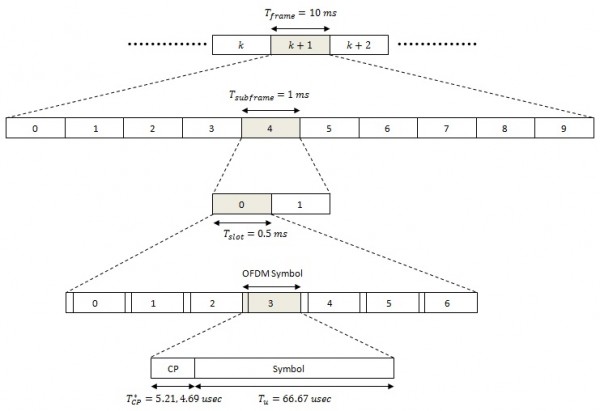
The LTE standard defines a resource allocation structure in time and frequency domains. If the spatial domain is also considered the resource allocation structure actually becomes a 3-dimensional arrangment. We will ignore the spatial domain for now and focus on the time-frequency plane.
In the time domain the LTE transmissions are organized into frames of 10 msec length. Each frame is composed of 10 subframes of 1 msec duration. Each subframe is made up of two equal sized slots of 0.5 msec each. Each slot is composed of 7 or 6 OFDM symbols depending upon whether a short or long Cyclic Prefix (CP) has been used. In the case of a short CP the CP has a duration of 5.21 usec for the first symbol and 4.69 usec for the remaining 6 symbols such that the total slot duration is 0.5 msec. For the long CP the CP has a duration of 16.67 usec for all 6 symbols. The useful symbol duration is fixed at 66.67 usec.
Short CP
1*(5.21+66.67)+6*(4.69+66.67)=500 usec
Long CP
6*(16.67+66.67)=500 usec
In the frequency domain the subcarriers are spaced at 15kHz giving a useful symbol duration of 1/15000=66.67 usec after the IFFT operation. A group of 12 subcarriers (12*15=180 kHz) over one time slot (0.5 msec) is referred to as a Resource Block (RB). With 1200 subcarriers available over a 20 MHz bandwidth the LTE transmitter has 100 RBs available over one time slot.
The smallest unit of resource is termed as the Resource Element which is composed of one subcarrier and one OFDM symbol. Thus an RB has 12×7=84 and 12×6=72 Resource Elements for short and long CP respectively.
Note:
1. The total number of subcarriers over a 20 MHz bandwidth is calculated as 20000 kHz/15 kHz = 1333 subcarriers, which is much greater than 1200. This is because all subcarriers are not used and some subcarriers act as guard carriers at the edges.
2. Longer CP is useful in environments with long delay spread.
Author: Yasir
More than 20 years of experience in various organizations in Pakistan, the USA, and Europe. Worked with the Mobile and Portable Radio Group (MPRG) of Virginia Tech and Qualcomm USA and was one of the first researchers to propose Space Time Block Codes for eight transmit antennas. Have publsihed a book “Recipes for Communication and Signal Processing” through Springer Nature.

11 thoughts on “LTE Resource Allocation in Time-Frequency Plane”
Hi John,
This is very to the point information that I needed. Thanx alot for the provided
information.
Infact, I am trying to implement the multi-carrier signals in MATLAB. I want to see the sub-carriers and Resource Blocks in matlab figure. How can I implement that? Can you refer me to some resource?
I will be very grateful.
To understand OFDM or in general multi-carrier systems you need to understand how FFT and IFFT work. Get a hold of any good signals and systems book to understand the fundamentals. Once you understand the fundamentals rest is just application.
Hi,
I want to understand every detail of LTE technology plus planning and optimization of LTE. Which book I need to refer ?
A good general book is Cellular Communications by Jeffrey H. Reed but you would need another book on planning and optimization.
Hi John,
You said that 20 MHz/15KHz= 1333 subcarriers but only 1200 subcarriers are used. I have seen at one blog, it says that IDFT size is 2048, and 2048 is the total number of subcarriers but 1200 are used and the rest are zero paded. I am confused that what’s the correct way of finding the total subcarriers or if I am confusing between the two ?
Regards
Farhan
Farhan,
Depends upon which standard you are talking about (LTE, WiMAX etc). Each standard has its own way of implementing OFDM. It’s important to learn the fundamentals, how OFDM works, how do you get orthogonality of subcarriers, how does Cyclic Prefix work, how does equalization work in the frequency domain. Do not worry too much about the implementation. Having said that, I do think that zero padding half of the subcarriers is NOT a very good idea.
John
John, how is number of guard subcarriers decided(calculated)? I looked at the following table:
http://www.tsiwireless.com/docs/whitepapers/LTE%20in%20a%20Nutshell%20-%20Physical%20Layer.pdf
why the 1.25MHz has 77% DL bandwidth efficiency while >2.5MHz has 90%? Are the difference because of guard bands? Thank you.
Thanks…
Hi John,
Thanks for your wonderful explanation..This is very easy to understnad..
Can u pls explain in details about the same in Uplink as well? As we are using SC-FDMA in Uplink then how can we allocate the Resource to UE..and what will be the Bit Rate in Uplink…
I’m confusing this area only..It would be nice if you explain this …
Thanks in advance..
Garv: That’s an excellent point. Actually for that channel model the long CP would be used. The long CP has a duration of 16.67 usec which would be sufficient for this case.
If normal CP for subsequent OFDM symbols of a slot except first, then for ETU channel model which has 9th tap position at 5 microsec. That time will there be any problem?