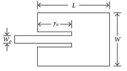
A Microstrip Patch Antenna or simply a Patch Antenna is a very common antenna type used in cell phones and many other electronic devices. It basically consists of two metallic plates separated by a dielectric layer. The metallic plates are usually made of copper or some other highly conductive material. Another important feature of this antenna is the feeding mechanism, which is also made of a highly conductive material. A Microstrip Patch Antenna fed by a 50 ohm transmission line and a quarterwave transformer is shown below.

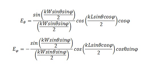
The E-field and H-field generated by the Patch Antenna can be calculated by using a simulation tool such as CST Microwave Studio. It is dependent on the length ‘L’ and width ‘W’ of the patch as well as on the wavelength ‘λ’ and the feeding mechanism. Other important parameters are the width of the substrate and the permittivity of the substrate. The E-field can be approximated as.

Part of the above equations is a sinc function which can be calculated by the MATLAB sinc function.
References:
[1] http://www.emtalk.com/mwt_mpa.htm
[2] http://www.antenna-theory.com/antennas/patches/antenna.php#introduction
Author: Yasir
More than 20 years of experience in various organizations in Pakistan, the USA, and Europe. Worked with the Mobile and Portable Radio Group (MPRG) of Virginia Tech and Qualcomm USA and was one of the first researchers to propose Space Time Block Codes for eight transmit antennas. Have publsihed a book “Recipes for Communication and Signal Processing” through Springer Nature.