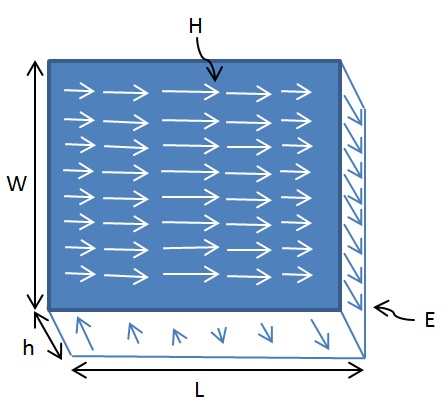
The Electric and Magnetic Field variations within a patch are sometimes a bit confusing and difficult to visualize. The figure below shows the E and H Field variations within a rectangular patch of length L and width W.
As can be seen the E-field varies along the length of the patch with minimum at the centre and maximum at the edges (maximum positive and maximum negative). The H-field also varies along the length is in a direction perpendicular to the E-field. The H-field is maximum at the center and minimum at the edges. Thus the impedance is zero at the center of the patch (using Z=V/I).
Another point to note is that the E-field does not completely terminate at the edges along the length of the antenna rather it extends at the outer periphery. These field extensions are known as fringing fields and cause the patch to radiate [1].
[1] http://www.orbanmicrowave.com/The_Basics_Of_Patch_Antennas.pdf
Author: Yasir
More than 20 years of experience in various organizations in Pakistan, the USA, and Europe. Worked with the Mobile and Portable Radio Group (MPRG) of Virginia Tech and Qualcomm USA and was one of the first researchers to propose Space Time Block Codes for eight transmit antennas. Have publsihed a book “Recipes for Communication and Signal Processing” through Springer Nature.
