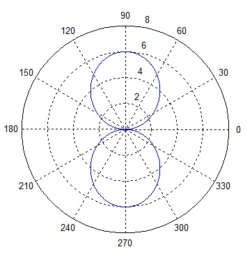
A dipole antenna is a simple antenna that can be built out of electrical wire. The most common dipole antenna is a half wave dipole which is constructed from a piece of wire half wavelength long. The wire is split in the center to connect the feeding wires. The E-field of the antenna has a circular pattern along a plane which cuts the axis of the antenna perpendicularly and is similar to a figure of 8 in a plane along the axis of the antenna [3D pattern]. The exact E-field can be calculated as:


The MATLAB code for generating the above pattern is given below.
n=377;
Io=1;
r=10;
lambda=0.3;
k=(2*pi)/lambda;
L=lambda/2;

theta=0:0.01:2*pi;
E=j*n*Io*exp(-j*k*r)*(1/(2*pi*r))*((cos(k*L*cos(theta)/2)-cos(k*L/2))./sin(theta));
polar(theta, abs(E))
Note that the above is true within an area at a sufficient distance from the antenna known as the far-field of the antenna. Closer to the antenna i.e. in the near-field the E-field expression is a bit more complex.
Author: Yasir Ahmed (aka John)
More than 20 years of experience in various organizations in Pakistan, the USA, and Europe. Worked as a Research Assistant within the Mobile and Portable Radio Group (MPRG) of Virginia Tech and was one of the first researchers to propose Space Time Block Codes for eight transmit antennas. The collaboration with MPRG continued even after graduating with an MSEE degree and has resulted in 12 research publications and a book on Wireless Communications. Worked for Qualcomm USA as an Engineer with the key role of performance and conformance testing of UMTS modems. Qualcomm is the inventor of CDMA technology and owns patents critical to the 4G and 5G standards.
What a shame you didn’t comment a bit more on the relation between the equation and the graph. Now, this is only useful for people who already know the subject. But then, what is the goal of this blog?
Thanks for your comment.
The Electrical Field (E) is a function of theta. At theta=0 degrees both the cosine terms inside the bracket cancel out and we get a null in the polar plot (on closer inspection it’s zero divided by zero). When theta=90 degrees one of the cosine terms inside the bracket goes to zero and the denominator is equal to one. For this case, we get maxima in the polar plot.
Yasir
what is the MATLAB command for plotting the same thing as a 3d radiation pattern?
Plot3
Hello, the journal was really easy to understand. Thank you for this work that you do. Though can I ask you how to get the impedance plot (graph) versus the frequency used for a half-wave dipole antenna in MATLAB?
I would really appreciate it if you can spare the time to help me with this.
Again thank you for the entry.