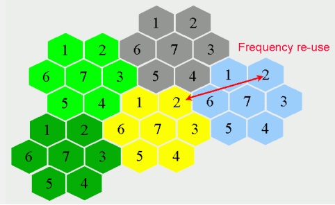
Frequency Reuse is a well known concept that has been applied to wireless systems over the past two decades e.g. in GSM systems. As the name suggests Frequency Reuse implies using the same frequencies over different geographical areas. If we have a 25MHz band then we can have 125 GSM channels and 125*8=1000 time multiplexed users in a given geographical area. Now if we want to increase the number of users we would have to reuse the same frequency band in a geographically separated area. The technique usually adopted is to use a fraction of the total frequency band in each cell such that no two neighbor cells use the same frequency. Typically the frequency band is divided into 3 or 7 cells.

The division of the frequency band in to smaller chunks reduces the system capacity e.g. one cell with 25 MHz bandwidth would have much higher capacity then 7 cells having 3.5 MHz each. To overcome this problem a frequency reuse of 1 has been proposed i.e. each cell has the full system bandwidth (nearly). The problem of co-channel interference at the cell boundaries is resolved by dedicating a small chunk of the available spectrum for the cell edges.

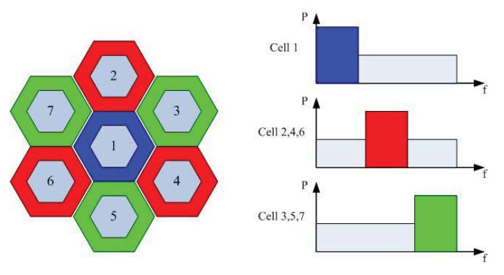
In Soft Frequency Reuse (SFR) the cell area is divided into two regions; a central region where all of the frequency band is available and a cell edge area where only a small fraction of the spectrum is available. The spectrum dedicated for the cell edge may also be used in the central region if it is not being used at the cell edge. The lack of spectrum at the cell edge may result in much reduced Shannon Capacity for that region. This is overcome by allocating high power carriers to the users in this region thus improving the SINR and the Shannon Capacity.
Note:
1. The Signal to Interference and Noise Ratio is given as:
SINR=Signal Power/(Intercell Interference+Intracell Interference+AWGN Noise)
2. Typically the term capacity was used to describe the number of voice channels (or users) that a system can support. But with modern digital communication systems it usually refers to the Shannon Capacity that can be achieved (in bits/sec/Hz).
[1] Yiwei Yu, Eryk Dutkiewicz, Xiaojing Huang, Markus Mueck and Gengfa Fang, “Performance Analysis of Soft Frequency Reuse for Inter-cell Interference Coordination in LTE Networks”, ISCIT 2010.
